
Resistor Color Code Calculator
Section A — Colour bands to resistance
Pick how many bands the resistor has, then pick the colour of each band from the lists. The first bands are the digits, the next is the multiplier, and the last is the tolerance.
Section B — Resistance value to colour bands (reverse)
Enter a resistance in ohms and pick the band count. The tool shows the colour bands for that value. The tolerance band shown is Gold (±5%), because a value alone does not fix the tolerance.
Educational use only; check the component datasheet for critical circuits.
A resistor color code calculator reads the coloured bands on a resistor and turns them into a resistance value. A resistor with yellow, violet, brown and gold bands is 470 Ω with a tolerance of ±5%, so its real resistance sits between 446.5 Ω and 493.5 Ω.
How do I use the Resistor Color Code Calculator?
Use Section A when you have a resistor in front of you and want its value. First pick the number of bands: 4, 5 or 6. Then pick the colour of each band from the lists, in order from the end you start reading from. Band 1 and Band 2 are the first two digits. On a 5-band or 6-band resistor, Band 3 is a third digit. The next band is the multiplier, and the last band is the tolerance. On a 6-band resistor there is one more band after the tolerance, for the temperature coefficient. Press the calculate button and the result boxes show the resistance, the tolerance, the minimum resistance and the maximum resistance. On a 6-band resistor a fifth box shows the temperature coefficient in ppm/K.
Use Section B when you know the resistance you need and want the colours to look for. Enter the resistance in ohms and pick the band count, then press the button. The tool shows the colour bands in order, with Gold as the tolerance band, and the value those bands give. A resistance value alone does not fix the tolerance, so Gold (±5%) is the band shown, and the note under the result says so. For a 6-band result the temperature-coefficient band is not set by the value either, so it is left for you to pick in Section A.
Both sections use the same arithmetic, and the article works through it step by step below. If a band colour is not chosen, the tool shows a message naming the missing band and shows no result. If the reverse value is zero or negative, the tool shows a message saying the value must be greater than 0 ohms. Educational use only; check the component datasheet for critical circuits.
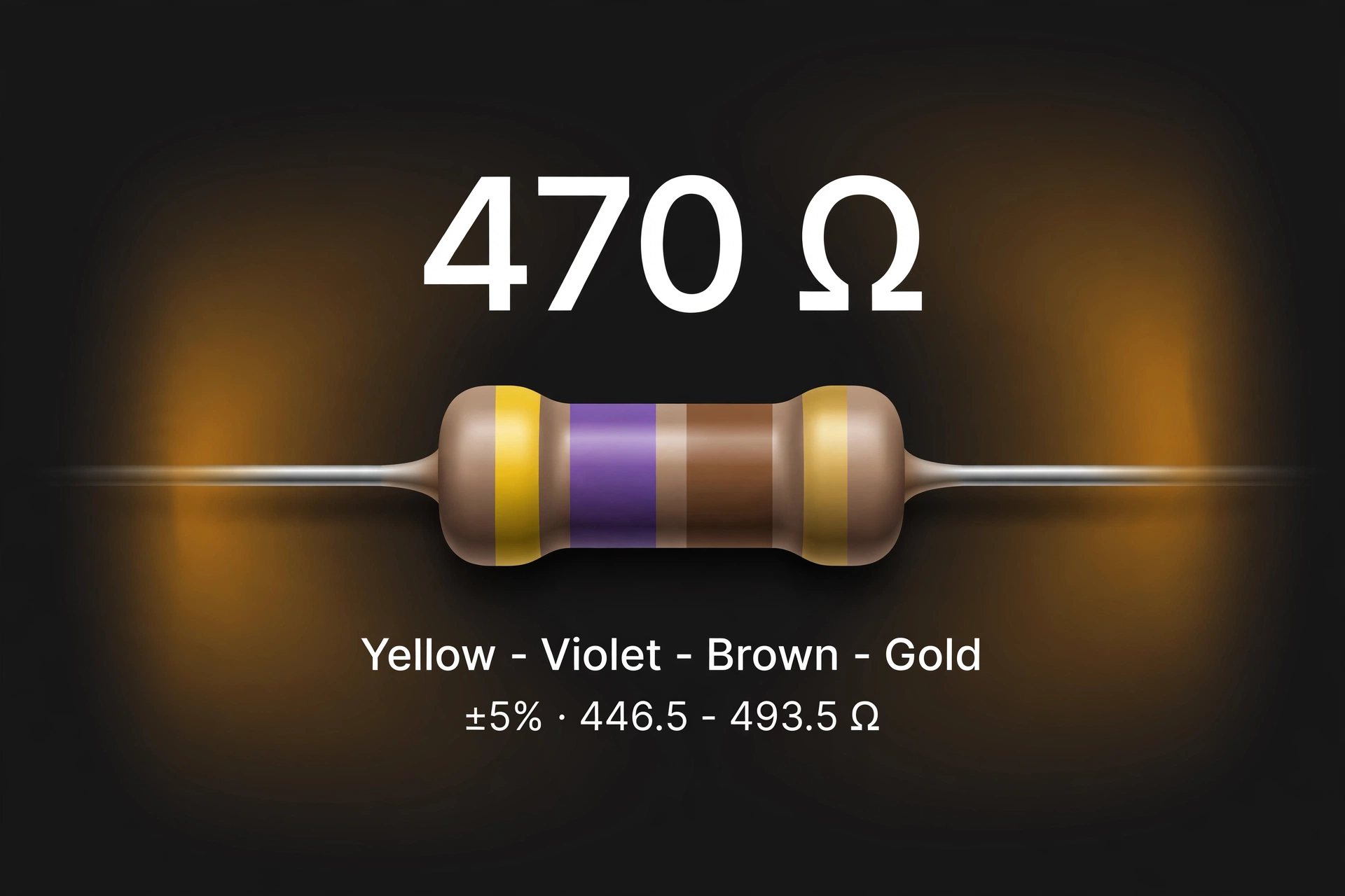
A worked example from the live tool
Take a 4-band resistor with yellow, violet, brown and gold bands. Choose 4-band in Section A, then set Band 1 to Yellow, Band 2 to Violet, the multiplier to Brown and the tolerance to Gold. Yellow is the digit 4 and violet is the digit 7, so the two digits together make 47. Brown as a multiplier means ×10. The resistance is 47 × 10, which is 470 Ω. Gold as a tolerance means ±5%. Five percent of 470 Ω is 23.5 Ω, so the minimum resistance is 470 − 23.5, which is 446.5 Ω, and the maximum is 470 + 23.5, which is 493.5 Ω. The tool shows 470 Ω, ±5%, 446.5 Ω and 493.5 Ω.
A second test uses five bands. Set Band 1 to Brown, Band 2 to Black, Band 3 to Black, the multiplier to Red and the tolerance to Brown. Brown is 1, black is 0 and black is 0, so the three digits make 100. Red as a multiplier means ×100. The resistance is 100 × 100, which is 10,000 Ω, shown as 10 kΩ. Brown as a tolerance means ±1%. One percent of 10,000 Ω is 100 Ω, so the minimum is 10,000 − 100, which is 9,900 Ω, shown as 9.9 kΩ, and the maximum is 10,000 + 100, which is 10,100 Ω, shown as 10.1 kΩ.
A third test uses six bands. Set Band 1 to Red, Band 2 to Violet, Band 3 to Black, the multiplier to Orange, the tolerance to Gold and the temperature-coefficient band to Brown. Red is 2, violet is 7 and black is 0, so the three digits make 270. Orange as a multiplier means ×1k, which is ×1,000. The resistance is 270 × 1,000, which is 270,000 Ω, shown as 270 kΩ. Gold means ±5%. Five percent of 270,000 Ω is 13,500 Ω, so the minimum is 270,000 − 13,500, which is 256,500 Ω, shown as 256.5 kΩ, and the maximum is 270,000 + 13,500, which is 283,500 Ω, shown as 283.5 kΩ. Brown as a temperature-coefficient band means 100 ppm/K, so the tool also shows 100 ppm/K.
Two more tests check the edges of the scale. Brown, black, green and gold give 1, 0, ×100k and ±5%: the digits make 10, the multiplier is 100,000, and 10 × 100,000 is 1,000,000 Ω, shown as 1 MΩ, with a range of 950,000 Ω to 1,050,000 Ω. Yellow, violet, gold and gold give 4, 7, ×0.1 and ±5%: the digits make 47, the multiplier is 0.1, and 47 × 0.1 is 4.7 Ω, with a range of 4.465 Ω to 4.935 Ω. Gold and silver as multipliers divide instead of multiplying, which is how values below 10 Ω are written in bands.
Reverse mode works from the same numbers. Enter 470 Ω with 4-band selected and the tool shows Yellow, Violet, Brown, Gold, which is the worked example above. Enter 4,700 Ω with 4-band selected and it shows Yellow, Violet, Red, Gold: the digits are still 4 and 7, but the multiplier is now red, ×100, so 47 × 100 is 4,700 Ω, shown as 4.7 kΩ, with a range of 4,465 Ω to 4,935 Ω at ±5%. Enter 473 Ω with 4-band selected and the tool shows the nearest value instead: 473 Ω does not map exactly to two significant digits, so the nearest 4-band value is 470 Ω, with the bands Yellow, Violet, Brown, Gold. Enter the same 473 Ω with 5-band selected and it maps exactly: the digits are 4, 7 and 3, the multiplier is black, ×1, and 473 × 1 is 473 Ω.
What do the colours on a resistor mean?
Each colour stands for a number, and its meaning depends on where it sits on the resistor. In a digit band a colour is one digit from 0 to 9. In the multiplier band the same colour is a power of ten. In the tolerance band it is a percentage. In the temperature-coefficient band it is a figure in ppm/K. The system is defined by IEC 60062, Marking codes for resistors and capacitors, and the table below follows that standard. A reference that sets out the same table is the resistor colour code page at Electronic Lab, which lists the values under IEC 60062:2016: https://www.electronic-lab.net/en/calculators/resistor-color-code/
| Colour | Digit | Multiplier | Tolerance | Temperature coefficient (ppm/K) |
|---|---|---|---|---|
| Black | 0 | ×1 | — | 250 |
| Brown | 1 | ×10 | ±1% | 100 |
| Red | 2 | ×100 | ±2% | 50 |
| Orange | 3 | ×1k | ±0.05% | 15 |
| Yellow | 4 | ×10k | ±0.02% | 25 |
| Green | 5 | ×100k | ±0.5% | 20 |
| Blue | 6 | ×1M | ±0.25% | 10 |
| Violet | 7 | ×10M | ±0.1% | 5 |
| Gray | 8 | ×100M | ±0.01% | 1 |
| White | 9 | ×1G | — | — |
| Gold | — | ×0.1 | ±5% | — |
| Silver | — | ×0.01 | ±10% | — |
| No band | — | — | ±20% | — |
Three things in the table deserve a closer look. First, the digit colours run in a fixed order: black 0, brown 1, red 2, orange 3, yellow 4, green 5, blue 6, violet 7, gray 8, white 9. From red onwards the order follows the rainbow, which gives a way to remember the middle of the sequence. Second, gold and silver are never digits. They appear only as multipliers, where gold means ×0.1 and silver means ×0.01, and as tolerances, where gold means ±5% and silver means ±10%. Their position on the resistor tells you which meaning applies. Third, the absence of a tolerance band has a meaning of its own: a resistor with no tolerance band is ±20%.
One value in the table needs a note. The table above lists grey as a tolerance as ±0.01%, following IEC 60062:2016, and the tolerance picker in the tool on this page uses the same figure. Older charts list grey as ±0.05%, and some manufacturers still use that older value, so if a resistor has a grey tolerance band, check the component datasheet before relying on either figure, because the two sources disagree and the datasheet for that part settles it. The same advice applies to orange and yellow as tolerances (±0.05% and ±0.02% in the table above), which appear on some precision parts and are easy to misread as digit bands.
How do I know which end to start reading from?
A resistor does not print an arrow, so the reading direction has to be worked out from the bands themselves. The most reliable clue is the tolerance band. On most resistors it is gold or silver, and it sits at one end, slightly apart from the other bands. Hold the resistor so that band is on the right, then read from left to right. The gap before the tolerance band is usually wider than the gaps between the digit and multiplier bands, and that wider gap marks the end of the value and the start of the tolerance.
If the tolerance band is not gold or silver, the spacing clue still works: the digit and multiplier bands sit close together in a group, and the tolerance band stands apart from that group. Start from the end where the bands are closest together and read towards the band that stands apart. A second check is the value itself. If the reading gives a value that is not in the standard E12 or E24 series — for example 43 Ω, or a reading that starts with a digit that makes no sense for the part — try reading from the other end. One direction will usually land on a standard value and the other will not. That check is not proof on its own, because precision parts can hold non-E12 values, but it catches most reversed readings.
What is the difference between 4-band, 5-band and 6-band resistors?
A 4-band resistor carries two significant digits, a multiplier and a tolerance. It is the most common type, and it is the type found in most general electronics kits. Its tolerance is usually gold (±5%) or silver (±10%), which matches its two-digit precision: a third digit would add detail the tolerance does not support. Yellow, violet, red, gold is a 4-band resistor, and it reads 4.7 kΩ ±5%.
A 5-band resistor carries three significant digits, a multiplier and a tolerance. The extra digit is there because the part is more precise, usually ±1% or ±2%, and a two-digit code could not express its value closely enough. The same 4.7 kΩ value in 5-band form reads yellow, violet, black, brown, brown: the digits are 4, 7 and 0, the multiplier is brown (×10), and 470 × 10 is 4,700 Ω, with a tolerance of ±1%. The trap here is the third band. On a 4-band resistor the third band is the multiplier; on a 5-band resistor the third band is a digit and the fourth band is the multiplier. Reading a 5-band resistor as if it had four bands gives a value ten times too large or too small.
A 6-band resistor is a 5-band resistor with one more band, for the temperature coefficient. The first five bands are the same as a 5-band resistor: three digits, a multiplier and a tolerance. The sixth band says how much the resistance moves with temperature, in ppm/K. It is used where a circuit has to hold its value as it warms up, and it is the only difference between a 5-band and a 6-band part. Older 3-band resistors also exist, with two digits and a multiplier and no tolerance band, which means ±20%; they are uncommon in new parts, and this tool does not offer a 3-band mode.
How is the resistance value built from the bands?
The value is built in two steps: write the digits side by side, then multiply by the multiplier. For a 4-band resistor the formula is resistance = (first digit × 10 + second digit) × multiplier. For the worked example, that is (4 × 10 + 7) × 10, which is 47 × 10, which is 470 Ω. For a 5-band or 6-band resistor the formula is resistance = (first digit × 100 + second digit × 10 + third digit) × multiplier. For the 10 kΩ test, that is (1 × 100 + 0 × 10 + 0) × 100, which is 100 × 100, which is 10,000 Ω.
The multiplier is a power of ten, and it is easiest to read as the number of zeros to add. Black adds no zeros (×1), brown adds one zero (×10), red adds two (×100), orange adds three (×1k) and so on up to white, which adds nine (×1G). Gold and silver work the other way: gold divides by 10 (×0.1) and silver divides by 100 (×0.01), which moves the decimal point left instead of adding zeros. That is how a resistor can read 4.7 Ω from the bands yellow, violet, gold, gold: the digits make 47, the multiplier is 0.1, and 47 × 0.1 is 4.7 Ω.
The result is then written with the unit that fits its size. Values below 1,000 Ω are shown in ohms, as in 470 Ω. Values from 1,000 Ω up to 999,999 Ω are shown in kilohms, as in 10 kΩ and 270 kΩ. Values of 1,000,000 Ω and above are shown in megohms, as in 1 MΩ. The tool follows that rule for the resistance and for the minimum and maximum as well, so a range of 9,900 Ω to 10,100 Ω is shown as 9.9 kΩ to 10.1 kΩ. For the electrical side of a circuit once the resistance is known, including the current and voltage that go with it, see the ohms law calculator.
What does tolerance mean, and how do I work out the minimum and maximum?
Tolerance is the range a real resistor is allowed to sit in, measured from the value the bands state. A 470 Ω resistor with ±5% tolerance is not guaranteed to measure exactly 470 Ω. It is guaranteed, within its specification, to measure somewhere between 446.5 Ω and 493.5 Ω. That range is the nominal value minus 5% and the nominal value plus 5%, and the tool shows both ends of it as the minimum and maximum resistance.
The arithmetic is the same for every tolerance. Take the nominal value, multiply it by the tolerance percentage divided by 100, and that gives the allowed drift in ohms. Subtract the drift for the minimum and add it for the maximum. For the 10 kΩ test at ±1%, the drift is 10,000 × 0.01, which is 100 Ω, so the range is 9,900 Ω to 10,100 Ω. For the 270 kΩ test at ±5%, the drift is 270,000 × 0.05, which is 13,500 Ω, so the range is 256,500 Ω to 283,500 Ω. A tighter tolerance gives a narrower range: the same 10 kΩ value at ±0.5% would sit between 9,950 Ω and 10,050 Ω, a drift of only 50 Ω each way.
Tolerance matters when a circuit depends on an exact value. A voltage divider, a timing circuit and a current-setting resistor all change their behaviour if the resistance is at the edge of its range rather than at its nominal value. In those cases the minimum and maximum from the tool are the figures to design with, not the nominal value alone. A part with a wide tolerance is fine where the exact value does not matter, such as a pull-up resistor or a current-limiting resistor for an LED, and that is why ±5% parts are the most common: they are cheap and good enough for those jobs. For a related cost figure when a resistor is part of a larger project, the electricity cost calculator works out what a device costs to run.
What is the temperature coefficient (ppm/K)?
The temperature coefficient, shown on the sixth band of a 6-band resistor, says how much the resistance changes as the resistor warms up or cools down. It is measured in ppm/K, which means parts per million per kelvin. One kelvin is the same size as one degree Celsius for a temperature change, so a figure in ppm/K works the same way for a change in degrees Celsius. A coefficient of 100 ppm/K means the resistance changes by 100 millionths of itself — 0.01% — for each kelvin of temperature change.
To turn that into ohms, multiply the resistance by the coefficient, divide by one million, and multiply by the temperature change. For the 270 kΩ test at 100 ppm/K, a rise of 50 K gives 270,000 × 100 ÷ 1,000,000 × 50, which is 1,350 Ω. That is a change of 0.5% for a 50 K rise, which is small next to a ±5% tolerance but large next to a ±0.1% tolerance. That is why the temperature coefficient matters most on precision parts: a 1% resistor that drifts 0.5% as it warms up has lost half its precision to temperature alone.
The common temperature-coefficient colours are brown (100 ppm/K), red (50), orange (15), yellow (25), blue (10) and violet (5). The full table also lists black (250 ppm/K), green (20) and gray (1), which are rarer. A smaller number means a more stable resistor: violet at 5 ppm/K moves twenty times less with temperature than brown at 100 ppm/K. The coefficient says nothing about how hot the resistor is allowed to get. That limit comes from its power rating, which the colours do not state, and it is covered in the section on what the colours do not tell you.
How does reverse mode work — from ohms back to colours?
Reverse mode starts from a resistance in ohms and finds the bands that give it. It works by writing the value with the right number of significant digits — two for a 4-band resistor, three for a 5-band or 6-band resistor — and then splitting it into digits and a multiplier. For 470 Ω with 4-band selected, the two significant digits are 4 and 7, and the rest of the value is a factor of 10, so the bands are Yellow, Violet, Brown, Gold. The last band is Gold because the value alone does not fix the tolerance, as explained above.
For 4,700 Ω the same digits appear with a different multiplier. The two significant digits are still 4 and 7, but the factor is now 100, so the multiplier band is red and the bands are Yellow, Violet, Red, Gold. For 4.7 Ω the digits are still 4 and 7, but the factor is 0.1, so the multiplier band is gold and the bands are Yellow, Violet, Gold, Gold. The first gold band is the multiplier (×0.1) and the second gold band is the tolerance (±5%). Position is what separates the two meanings, which is why the order of the bands in the result matters.
Not every value maps exactly. A 4-band code can only express two significant digits, so 473 Ω has no exact 4-band code: its first two digits are 4 and 7, and the third digit, 3, has nowhere to go. The tool rounds to the nearest two-digit value, 470 Ω, and says so in a note under the result, showing the bands for 470 Ω. The same value maps exactly in 5-band form, because three digits are enough: 4, 7 and 3 with a multiplier of ×1 gives 473 Ω. The rule is simple: if the value needs more significant digits than the band count allows, the tool shows the nearest value it can express and says that it has done so, rather than showing a code that claims to be exact.
What are the standard E12 values?
Resistors are not made in every value. They are made in preferred-value series, spaced so that the tolerance ranges of neighbouring values just about meet. The E12 series is the standard series for ±10% and ±5% parts, with 12 values in each decade: 10, 12, 15, 18, 22, 27, 33, 39, 47, 56, 68 and 82. Each decade multiplies those twelve numbers by the same factor, so the series repeats at every scale. The table below lists the E12 values from 10 Ω to 820 kΩ, with every cell computed by multiplying the base value by the decade factor.
| Base value | ×1 (Ω) | ×10 (Ω) | ×100 (Ω) | ×1k (Ω) | ×10k (Ω) |
|---|---|---|---|---|---|
| 10 | 10 | 100 | 1,000 | 10,000 | 100,000 |
| 12 | 12 | 120 | 1,200 | 12,000 | 120,000 |
| 15 | 15 | 150 | 1,500 | 15,000 | 150,000 |
| 18 | 18 | 180 | 1,800 | 18,000 | 180,000 |
| 22 | 22 | 220 | 2,200 | 22,000 | 220,000 |
| 27 | 27 | 270 | 2,700 | 27,000 | 270,000 |
| 33 | 33 | 330 | 3,300 | 33,000 | 330,000 |
| 39 | 39 | 390 | 3,900 | 39,000 | 390,000 |
| 47 | 47 | 470 | 4,700 | 47,000 | 470,000 |
| 56 | 56 | 560 | 5,600 | 56,000 | 560,000 |
| 68 | 68 | 680 | 6,800 | 68,000 | 680,000 |
| 82 | 82 | 820 | 8,200 | 82,000 | 820,000 |
The worked example sits in this table: 470 Ω is the 47 row in the ×10 column, and 4.7 kΩ is the same row in the ×100 column. If a reading gives a value that is not in this table or in the finer E24 series (which adds 11, 13, 16, 20, 24, 30, 36, 43, 51, 62, 75 and 91 to each decade), the reading is probably wrong. A result of 473 Ω, for example, is not an E12 or E24 value, which is a sign that a band was misread or that the part is a precision resistor with a 5-band code. The E96 series, used for ±1% parts, has 96 values per decade and covers values such as 475 Ω, so a 5-band reading that is not in E12 or E24 is not automatically wrong — it only needs a second check.
What mistakes do people make when reading resistor bands?
The most common mistake is reading the resistor backwards. The bands look much the same from either end, and a reversed reading gives a different value that can still look plausible. The defence is the tolerance band and the gap before it: put the gold or silver band on the right, read from the left, and check the result against the E12 table. If the reversed reading lands on a standard value and the first reading does not, the reversed reading is the right one.
The second mistake is confusing colours that look alike. Red and brown, and orange and red, are the pairs that cause the most trouble, and the difference between them is a factor of ten in the digit or the multiplier. Read the bands in good light, and compare a doubtful band with one whose colour is known: the tolerance band is usually gold or silver, so it gives a reference for what gold looks like, and the body colour of the resistor gives a reference for beige, which is close to brown but is not a band colour.
The third mistake is treating gold and silver as digits. They are never digits, so a band of gold or silver in the first two positions means the resistor is being read from the wrong end. If the first band looks gold or silver, turn the resistor around. The fourth mistake is forgetting that the third band changes meaning between 4-band and 5-band parts. On a 4-band resistor it is the multiplier; on a 5-band resistor it is a digit. Counting the bands first, before reading any of them, avoids this error entirely.
The fifth mistake is reading the multiplier as the number of zeros without checking for gold and silver. A gold multiplier divides by 10 and a silver multiplier divides by 100, so a resistor that looks like 47 Ω from its digits can really be 4.7 Ω or 0.47 Ω. The sixth mistake is ignoring the tolerance and quoting the nominal value as if it were exact. A 470 Ω ±5% resistor can measure 450 Ω and still be within specification, and a circuit that needs better than that needs a tighter-tolerance part, not a different reading of the same bands.
What do the colours NOT tell you?
The colours give the resistance, the tolerance and, on 6-band parts, the temperature coefficient. They do not give the power rating. A resistor's power rating — commonly 1/8 W, 1/4 W, 1/2 W or 1 W for the small axial parts in a kit — depends on its physical size, not on its bands. A 470 Ω resistor in a tiny body and a 470 Ω resistor in a large body can carry the same bands and have different power ratings. Using a part above its power rating makes it overheat, whatever the bands say, so the rating has to come from the datasheet or the supplier's listing for that part size.
The colours also say nothing about how the resistor will behave in a real circuit. They do not state the temperature of the part in use, the voltage across it, or the power it is dissipating. Those figures come from the circuit itself: power is voltage squared divided by resistance, and current is voltage divided by resistance. The ohms law calculator works those figures out from the resistance this tool gives. Educational use only; check the component datasheet for critical circuits.
They also do not give the voltage rating, which is the highest voltage the resistor can safely have across it. That limit also comes from the part's construction and the datasheet, and it matters in high-voltage circuits even when the power is low. The colours say nothing about the resistor's construction either — carbon film, metal film, wirewound and metal oxide parts can share the same band code — and construction affects noise, stability and behaviour at high frequencies. For converting between the units that appear on a datasheet, such as ohms, kilohms and megohms, see the unit converter.
How can I check a resistor with a multimeter?
A multimeter gives a second reading that does not depend on colour vision or on the reading direction. Set the meter to resistance, touch the probes to the two leads of the resistor, and read the display. The measured value should sit inside the minimum-to-maximum range the tool shows for the bands. For the worked example, a yellow, violet, brown, gold resistor should measure between 446.5 Ω and 493.5 Ω. A reading inside that range supports the band reading. A reading outside it means either the bands were misread or the part is faulty.
What are the limits of this calculator?
This tool reads the standard IEC 60062 colour code for axial-lead resistors with 4, 5 or 6 bands. It does not read surface-mount resistors, which use printed numbers instead of colours — for example 472 printed on a chip means 47 × 100, which is 4.7 kΩ — and it does not read the EIA-96 three-character code used on some 1% surface-mount parts. It does not offer a 3-band mode, so an old 3-band resistor with no tolerance band has to be read as a 4-band resistor with the tolerance set to None (±20%).
The tool also takes the bands at face value. It cannot tell whether a colour has faded, whether red has been confused with orange, or whether the resistor is being read from the wrong end. Its result is only as good as the colours entered, which is why the article gives the E12 check and the multimeter check as ways to catch a misreading. The reverse mode has its own limit: it can only show values that fit in two significant digits for 4-band and three for 5-band and 6-band, and it shows Gold (±5%) as the tolerance because the value alone does not fix the tolerance. The temperature-coefficient band in reverse mode is not set by the value at all.
Finally, the tolerance range the tool shows is the range the specification allows, not a measurement of the part in hand. A real resistor usually measures closer to its nominal value than to the edge of its range, and a part that measures outside its range is out of specification. The tool does not model drift with age, with humidity, or with self-heating under load; those effects are small for most hobby use and are covered by the datasheet for the part. More tools in the same collection are in the calculators category.
Frequently asked questions
1. How do I read a resistor colour code?
Find the tolerance band, usually gold or silver, and hold it on the right, then read the bands from left to right. The first two bands on a 4-band resistor (or three on a 5-band resistor) are the significant digits, the next band is the multiplier, and the last band is the tolerance. Yellow, violet, brown, gold is 4, 7, ×10, ±5%, which is 470 Ω ±5%.
2. What is yellow, violet, brown, gold on a resistor?
It is a 470 Ω resistor with a tolerance of ±5%. Yellow is the digit 4, violet is the digit 7, brown as a multiplier means ×10, and gold as a tolerance means ±5%. The value is 47 × 10, which is 470 Ω, and the allowed range is 446.5 Ω to 493.5 Ω.
3. What is the difference between a 4-band and a 5-band resistor?
A 4-band resistor has two significant digits, a multiplier and a tolerance, while a 5-band resistor has three significant digits, a multiplier and a tolerance. The extra digit lets a 5-band resistor express a more precise value, which is why 5-band parts usually carry a tighter tolerance such as ±1%. The same 4.7 kΩ value reads yellow, violet, red, gold in 4-band form and yellow, violet, black, brown, brown in 5-band form.
4. What do gold and silver mean on a resistor?
It depends on their position. As a multiplier band, gold means ×0.1 and silver means ×0.01. As a tolerance band, gold means ±5% and silver means ±10%. Gold and silver are never digits, so if one appears in the first two positions the resistor is being read from the wrong end.
5. How do I work out the minimum and maximum resistance from the tolerance?
Multiply the nominal value by the tolerance percentage divided by 100 to get the allowed drift, then subtract it for the minimum and add it for the maximum. For 470 Ω at ±5%, the drift is 470 × 0.05, which is 23.5 Ω, so the range is 446.5 Ω to 493.5 Ω.
6. What does ppm/K mean on a 6-band resistor?
It is the temperature coefficient: how many parts per million the resistance changes for each kelvin (or degree Celsius) of temperature change. A 6-band resistor with a brown sixth band has a coefficient of 100 ppm/K, so a 270 kΩ resistor with that band changes by 1,350 Ω for a 50 K temperature rise. A smaller ppm/K figure means a more temperature-stable resistor.
How do I read a resistor colour code?
Find the tolerance band, usually gold or silver, and hold it on the right, then read the bands from left to right. The first two bands on a 4-band resistor (or three on a 5-band resistor) are the significant digits, the next band is the multiplier, and the last band is the tolerance. Yellow, violet, brown, gold is 4, 7, ×10, ±5%, which is 470 Ω ±5%.
What is yellow, violet, brown, gold on a resistor?
It is a 470 Ω resistor with a tolerance of ±5%. Yellow is the digit 4, violet is the digit 7, brown as a multiplier means ×10, and gold as a tolerance means ±5%. The value is 47 × 10, which is 470 Ω, and the allowed range is 446.5 Ω to 493.5 Ω.
What is the difference between a 4-band and a 5-band resistor?
A 4-band resistor has two significant digits, a multiplier and a tolerance, while a 5-band resistor has three significant digits, a multiplier and a tolerance. The extra digit lets a 5-band resistor express a more precise value, which is why 5-band parts usually carry a tighter tolerance such as ±1%. The same 4.7 kΩ value reads yellow, violet, red, gold in 4-band form and yellow, violet, black, brown, brown in 5-band form.
What do gold and silver mean on a resistor?
It depends on their position. As a multiplier band, gold means ×0.1 and silver means ×0.01. As a tolerance band, gold means ±5% and silver means ±10%. Gold and silver are never digits, so if one appears in the first two positions the resistor is being read from the wrong end.
How do I work out the minimum and maximum resistance from the tolerance?
Multiply the nominal value by the tolerance percentage divided by 100 to get the allowed drift, then subtract it for the minimum and add it for the maximum. For 470 Ω at ±5%, the drift is 470 × 0.05, which is 23.5 Ω, so the range is 446.5 Ω to 493.5 Ω.
What does ppm/K mean on a 6-band resistor?
It is the temperature coefficient: how many parts per million the resistance changes for each kelvin (or degree Celsius) of temperature change. A 6-band resistor with a brown sixth band has a coefficient of 100 ppm/K, so a 270 kΩ resistor with that band changes by 1,350 Ω for a 50 K temperature rise. A smaller ppm/K figure means a more temperature-stable resistor.